In the last post I had started implementing an Unscented Kalman Filter for position and orientation tracking in OpenHMD. Over the Christmas break, I continued that work.
A Quick Recap
When reading below, keep in mind that the goal of the filtering code I’m writing is to combine 2 sources of information for tracking the headset and controllers.
The first piece of information is acceleration and rotation data from the IMU on each device, and the second is observations of the device position and orientation from 1 or more camera sensors.
The IMU motion data drifts quickly (at least for position tracking) and can’t tell which way the device is facing (yaw, but can detect gravity and get pitch/roll).
The camera observations can tell exactly where each device is, but arrive at a much lower rate (52Hz vs 500/1000Hz) and can take a long time to process (hundreds of milliseconds) to analyse to acquire or re-acquire a lock on the tracked device(s).
The goal is to acquire tracking lock, then use the motion data to predict the motion closely enough that we always hit the ‘fast path’ of vision analysis. The key here is closely enough – the more closely the filter can track and predict the motion of devices between camera frames, the better.
Integration in OpenHMD
When I wrote the last post, I had the filter running as a standalone application, processing motion trace data collected by instrumenting a running OpenHMD app and moving my headset and controllers around. That’s a really good way to work, because it lets me run modifications on the same data set and see what changed.
However, the motion traces were captured using the current fusion/prediction code, which frequently loses tracking lock when the devices move – leading to big gaps in the camera observations and more interpolation for the filter.
By integrating the Kalman filter into OpenHMD, the predictions are improved leading to generally much better results. Here’s one trace of me moving the headset around reasonably vigourously with no tracking loss at all.

If it worked this well all the time, I’d be ecstatic! The predicted position matched the observed position closely enough for every frame for the computer vision to match poses and track perfectly. Unfortunately, this doesn’t happen every time yet, and definitely not with the controllers – although I think the latter largely comes down to the current computer vision having more troubler matching controller poses. They have fewer LEDs to match against compared to the headset, and the LEDs are generally more side-on to a front-facing camera.
Taking a closer look at a portion of that trace, the drift between camera frames when the position is interpolated using the IMU readings is clear.
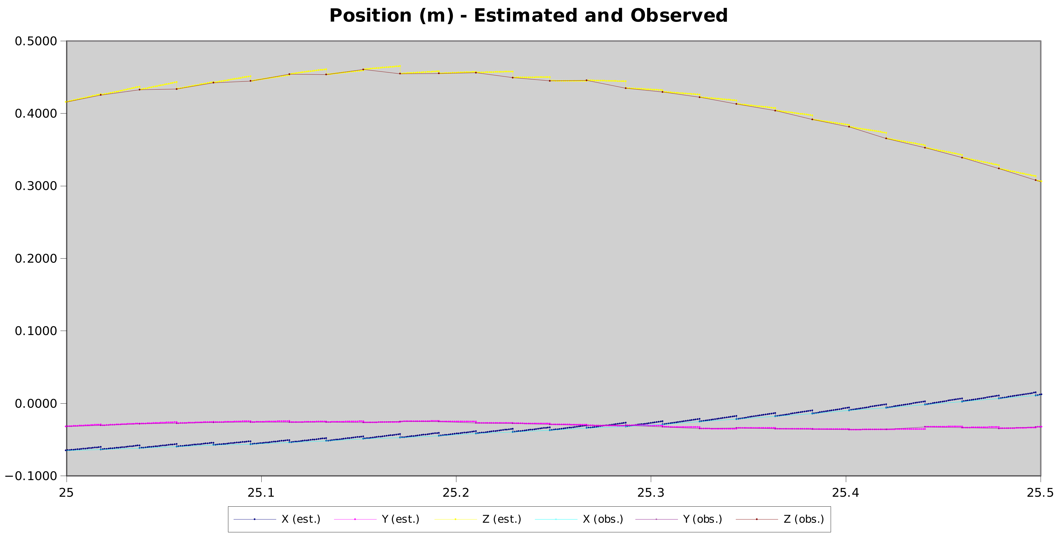
This is really good. Most of the time, the drift between frames is within 1-2mm. The computer vision can only match the pose of the devices to within a pixel or two – so the observed jitter can also come from the pose extraction, not the filtering.
The worst tracking is again on the Z axis – distance from the camera in this case. Again, that makes sense – with a single camera matching LED blobs, distance is the most uncertain part of the extracted pose.
Losing Track
The trace above is good – the computer vision spots the headset and then the filtering + computer vision track it at all times. That isn’t always the case – the prediction goes wrong, or the computer vision fails to match (it’s definitely still far from perfect). When that happens, it needs to do a full pose search to reacquire the device, and there’s a big gap until the next pose report is available.
That looks more like this
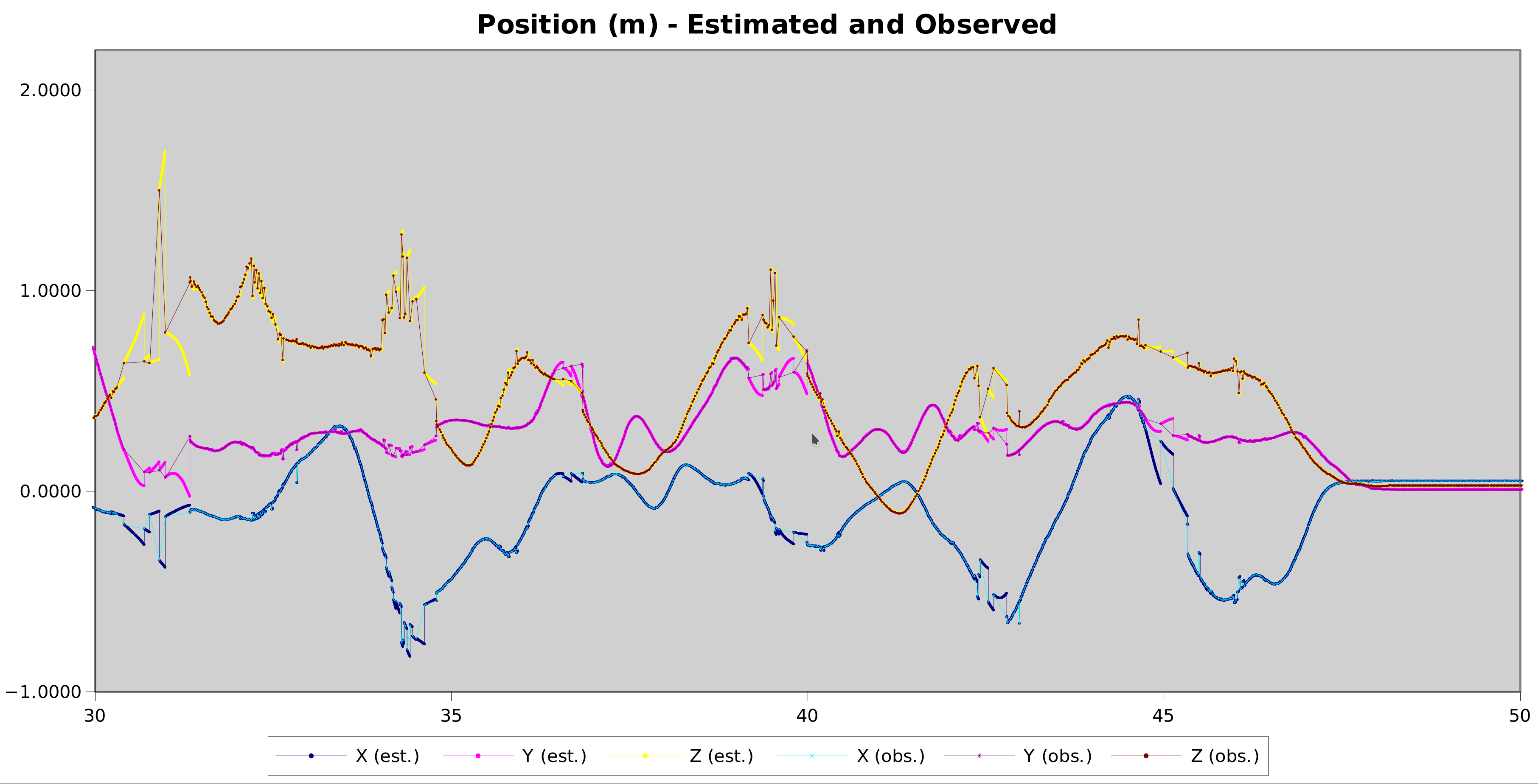
This trace has 2 kinds of errors – gaps in the observed position timeline during full pose searches and erroneous position reports where the computer vision matched things incorrectly.
Fixing the errors in position reports will require improving the computer vision algorithm and would fix most of the plot above. Outlier rejection is one approach to investigate on that front.
Latency Compensation
There is inherent delay involved in processing of the camera observations. Every 19.2ms, the headset emits a radio signal that triggers each camera to capture a frame. At the same time, the headset and controller IR LEDS light up brightly to create the light constellation being tracked. After the frame is captured, it is delivered over USB over the next 18ms or so and then submitted for vision analysis. In the fast case where we’re already tracking the device the computer vision is complete in a millisecond or so. In the slow case, it’s much longer.
Overall, that means that there’s at least a 20ms offset between when the devices are observed and when the position information is available for use. In the plot above, this delay is ignored and position reports are fed into the filter when they are available. In the worst case, that means the filter is being told where the headset was hundreds of milliseconds earlier.
To compensate for that delay, I implemented a mechanism in the filter where it keeps extra position and orientation entries in the state that can be used to retroactively apply the position observations.
The way that works is to make a prediction of the position and orientation of the device at the moment the camera frame is captured and copy that prediction into the extra state variable. After that, it continues integrating IMU data as it becomes available while keeping the auxilliary state constant.
When a the camera frame analysis is complete, that delayed measurement is matched against the stored position and orientation prediction in the state and the error used to correct the overall filter. The cool thing is that in the intervening time, the filter covariance matrix has been building up the right correction terms to adjust the current position and orientation.
Here’s a good example of the difference:

Notice how most of the disconnected segments have now slotted back into position in the timeline. The ones that haven’t can either be attributed to incorrect pose extraction in the compute vision, or to not having enough auxilliary state slots for all the concurrent frames.
At any given moment, there can be a camera frame being analysed, one arriving over USB, and one awaiting “long term” analysis. The filter needs to track an auxilliary state variable for each frame that we expect to get pose information from later, so I implemented a slot allocation system and multiple slots.
The downside is that each slot adds 6 variables (3 position and 3 orientation) to the covariance matrix on top of the 18 base variables. Because the covariance matrix is square, the size grows quadratically with new variables. 5 new slots means 30 new variables – leading to a 48 x 48 covariance matrix instead of 18 x 18. That is a 7-fold increase in the size of the matrix (48 x 48 = 2304 vs 18 x 18 = 324) and unfortunately about a 10x slow-down in the filter run-time.
At that point, even after some optimisation and vectorisation on the matrix operations, the filter can only run about 3x real-time, which is too slow. Using fewer slots is quicker, but allows for fewer outstanding frames. With 3 slots, the slow-down is only about 2x.
There are some other possible approaches to this problem:
- Running the filtering delayed, only integrating IMU reports once the camera report is available. This has the disadvantage of not reporting the most up-to-date estimate of the user pose, which isn’t great for an interactive VR system.
- Keeping around IMU reports and rewinding / replaying the filter for late camera observations. This limits the overall increase in filter CPU usage to double (since we at most replay every observation twice), but potentially with large bursts when hundreds of IMU readings need replaying.
- It might be possible to only keep 2 “full” delayed measurement slots with both position and orientation, and to keep some position-only slots for others. The orientation of the headset tends to drift much more slowly than position does, so when there’s a big gap in the tracking it would be more important to be able to correct the position estimate. Orientation is likely to still be close to correct.
- Further optimisation in the filter implementation. I was hoping to keep everything dependency-free, so the filter implementation uses my own naive 2D matrix code, which only implements the features needed for the filter. A more sophisticated matrix library might perform better – but it’s hard to say without doing some testing on that front.
Controllers
So far in this post, I’ve only talked about the headset tracking and not mentioned controllers. The controllers are considerably harder to track right now, but most of the blame for that is in the computer vision part. Each controller has fewer LEDs than the headset, fewer are visible at any given moment, and they often aren’t pointing at the camera front-on.
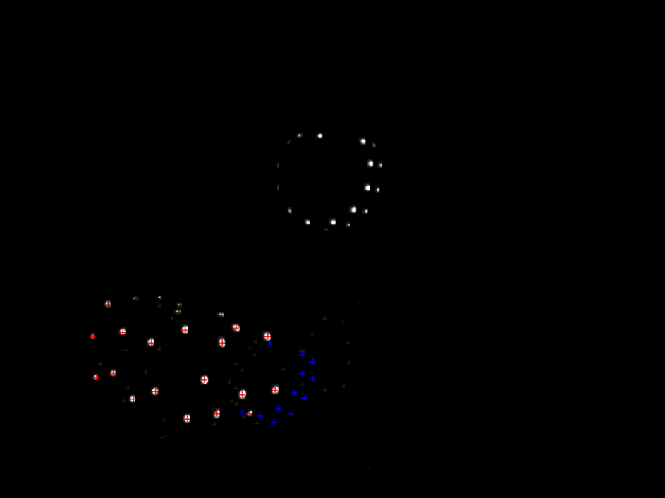
This screenshot is a prime example. The controller is the cluster of lights at the top of the image, and the headset is lower left. The computer vision has gotten confused and thinks the controller is the ring of random blue crosses near the headset. It corrected itself a moment later, but those false readings make life very hard for the filtering.
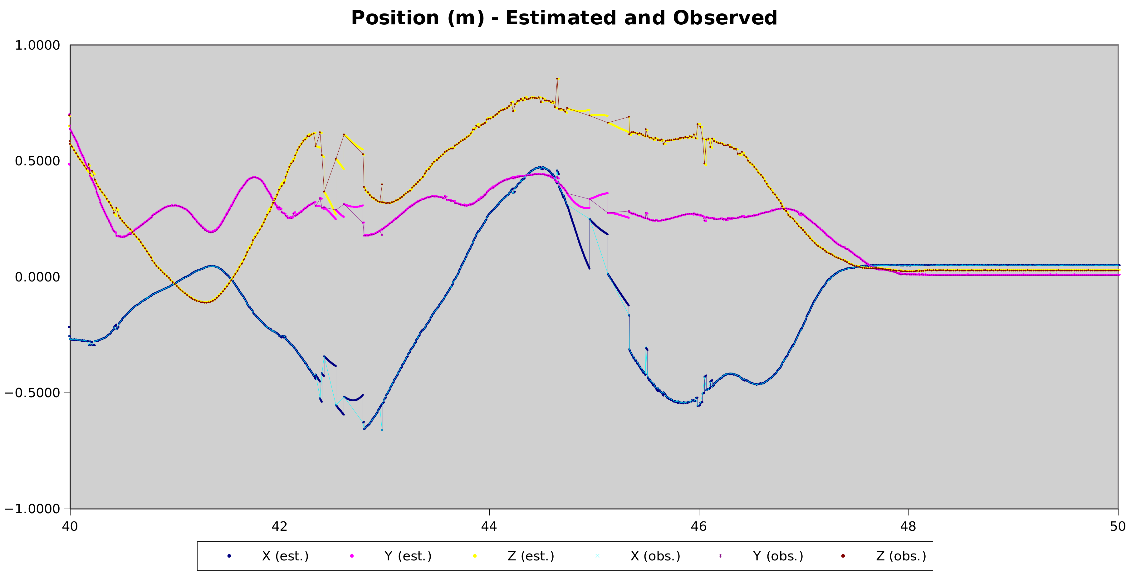
Here’s a typical example of the controller tracking right now. There are some very promising portions of good tracking, but they are interspersed with bursts of tracking losses, and wild drifting from the computer vision giving wrong poses – leading to the filter predicting incorrect acceleration and hence cascaded tracking losses. Particularly (again) on the Z axis.
Timing Improvements
One of the problems I was looking at in my last post is variability in the arrival timing of the various USB streams (Headset reports, Controller reports, camera frames). I improved things in OpenHMD on that front, to use timestamps from the devices everywhere (removing USB timing jitter from the inter-sample time).
There are still potential problems in when IMU reports from controllers get updated in the filters vs the camera frames. That can be on the order of 2-4ms jitter. Time will tell how big a problem that will be – after the other bigger tracking problems are resolved.
Sponsorships
All the work that I’m doing implementing this positional tracking is a combination of my free time, hours contributed by my employer Centricular and contributions from people via Github Sponsorships. If you’d like to help me spend more hours on this and fewer on other paying work, I appreciate any contributions immensely!
Next Steps
The next things on my todo list are:
- Integrate the delayed-observation processing into OpenHMD (at the moment it is only in my standalone simulator).
- Improve the filter code structure – this is my first kalman filter and there are some implementation decisions I’d like to revisit.
- Publish the UKF branch for other people to try.
- Circle back to the computer vision and look at ways to improve the pose extraction and better reject outlying / erroneous poses, especially for the controllers.
- Think more about how to best handle / schedule analysis of frames from multiple cameras. At the moment each camera operates as a separate entity, capturing frames and analysing them in threads without considering what is happening in other cameras. That means any camera that can’t see a particular device starts doing full pose searches – which might be unnecessary if another camera still has a good view of the device. Coordinating those analyses across cameras could yield better CPU consumption, and let the filter retain fewer delayed observation slots.