For some time now, I’ve been involved in the OpenHMD project, working on building an open driver for the Oculus Rift CV1, and more recently the newer Rift S VR headsets.
This post is a bit of an overview of how the 2 devices work from a high level for people who might have used them or seen them, but not know much about the implementation. I also want to talk about OpenHMD and how it fits into the evolving Linux VR/AR API stack.
OpenHMD
In short, OpenHMD is a project providing open drivers for various VR headsets through a single simple API. I don’t know of any other project that provides support for as many different headsets as OpenHMD, so it’s the logical place to contribute for largest effect.
OpenHMD is supported as a backend in Monado, and in SteamVR via the SteamVR-OpenHMD plugin. Working drivers in OpenHMD opens up a range of VR games – as well as non-gaming applications like Blender. I think it’s important that Linux and friends not get left behind – in what is basically a Windows-only activity right now.
One downside is that does come with the usual disadvantages of an abstraction API, in that it doesn’t fully expose the varied capabilities of each device, but instead the common denominator. I hope we can fix that in time by extending the OpenHMD API, without losing its simplicity.
Oculus Rift S
I bought an Oculus Rift S in April, to supplement my original consumer Oculus Rift (the CV1) from 2017. At that point, the only way to use it was in Windows via the official Oculus driver as there was no open source driver yet. Since then, I’ve largely reverse engineered the USB protocol for it, and have implemented a basic driver that’s upstream in OpenHMD now.
I find the Rift S a somewhat interesting device. It’s not entirely an upgrade over the older CV1. The build quality, and some of the specifications are actually worse than the original device – but one area that it is a clear improvement is in the tracking system.
CV1 Tracking
The Rift CV1 uses what is called an outside-in tracking system, which has 2 major components. The first is input from Inertial Measurement Units (IMU) on each device – the headset and the 2 hand controllers. The 2nd component is infrared cameras (Rift Sensors) that you space around the room and then run a calibration procedure that lets the driver software calculate their positions relative to the play area.
IMUs provide readings of linear acceleration and angular velocity, which can be used to determine the orientation of a device, but don’t provide absolute position information. You can derive relative motion from a starting point using an IMU, but only over a short time frame as the integration of the readings is quite noisy.
This is where the Rift Sensors get involved. The cameras observe constellations of infrared LEDs on the headset and hand controllers, and use those in concert with the IMU readings to position the devices within the playing space – so that as you move, the virtual world accurately reflects your movements. The cameras and LEDs synchronise to a radio pulse from the headset, and the camera exposure time is kept very short. That means the picture from the camera is completely black, except for very bright IR sources. Hopefully that means only the LEDs are visible, although light bulbs and open windows can inject noise and make the tracking harder.

If you have both IMU and camera data, you can build what we call a 6 Degree of Freedom (6DOF) driver. With only IMUs, a driver is limited to providing 3 DOF – allowing you to stand in one place and look around, but not to move.
OpenHMD provides a 3DOF driver for the CV1 at this point, with experimental 6DOF work in a branch in my fork. Getting to a working 6DOF driver is a real challenge. The official drivers from Oculus still receive regular updates to tweak the tracking algorithms.
I have given several presentations about the progress on implementing positional tracking for the CV1. Most recently at Linux.conf.au 2020 in January. There’s a recording at https://www.youtube.com/watch?v=PTHE-cdWN_s if you’re interested, and I plan to talk more about that in a future post.
Rift S Tracking
The Rift S uses Inside Out tracking, which inverts the tracking process by putting the cameras on the headset instead of around the room. With the cameras in fixed positions on the headset, the cameras and their view of the world moves as the user’s head moves. For the Rift S, there are 5 individual cameras pointing outward in different directions to provide (overall) a very wide-angle view of the surroundings.
The role of the tracking algorithm in the driver in this scenario is to use the cameras to look for visual landmarks in the play area, and to combine that information with the IMU readings to find the position of the headset. This is called Visual Inertial Odometry.
There is then a 2nd part to the tracking – finding the position of the hand controllers. This part works the same as on the CV1 – looking for constellations of LED lights on the controllers and matching what you see to a model of the controllers.
This is where I think the tracking gets particularly interesting. The requirements for finding where the headset is in the room, and the goal of finding the controllers require 2 different types of camera view!
To find the landmarks in the room, the vision algorithm needs to be able to see everything clearly and you want a balanced exposure from the cameras. To identify the controllers, you want a very fast exposure synchronised with the bright flashes from the hand controller LEDs – the same as when doing CV1 tracking.
The Rift S satisfies both requirements by capturing alternating video frames with fast and normal exposures. Each time, it captures the 5 cameras simultaneously and stitches them together into 1 video frame to deliver over USB to the host computer. The driver then needs to split each frame according to whether it is a normal or fast exposure and dispatch it to the appropriate part of the tracking algorithm.
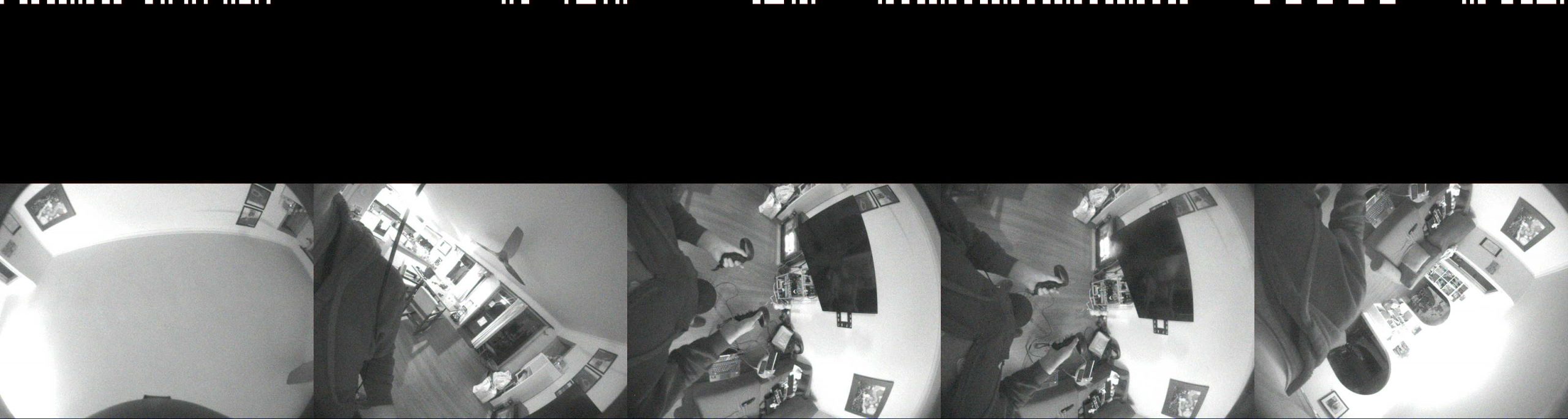
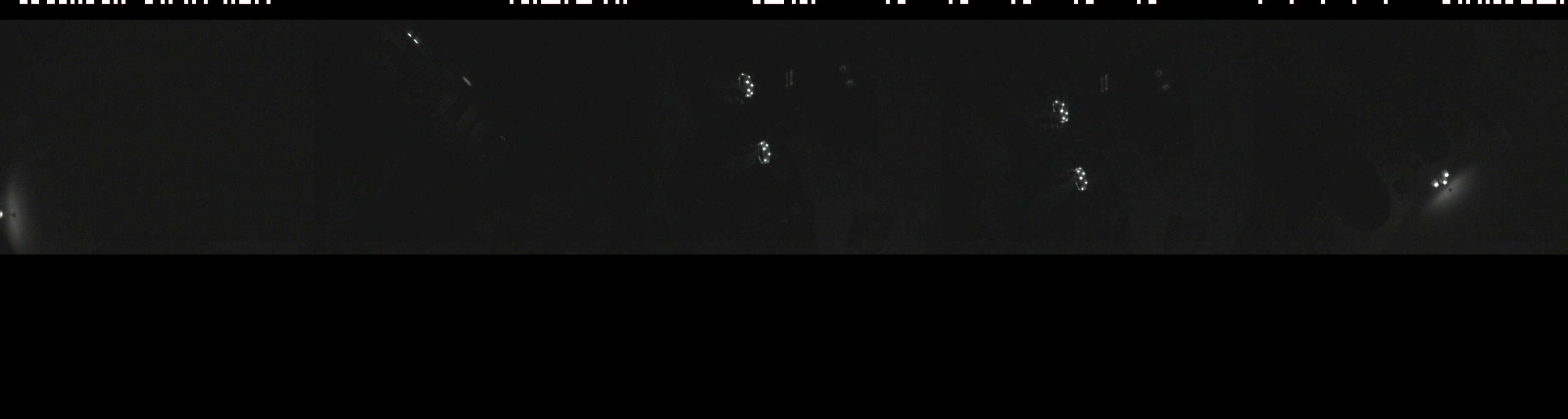
There are a bunch of interesting things to notice in these camera captures:
- Each camera view is inserted into the frame in some native orientation, and requires external information to make use of the information in them
- The cameras have a lot of fisheye distortion that will need correcting.
- In the fast exposure frame, the light bulbs on my ceiling are hard to tell apart from the hand controller LEDs – another challenge for the computer vision algorithm.
- The cameras are Infrared only, which is why the Rift S passthrough view (if you’ve ever seen it) is in grey-scale.
- The top 16-pixels of each frame contain some binary data to help with frame identification. I don’t know how to interpret the contents of that data yet.
Status
This blog post is already too long, so I’ll stop here. In part 2, I’ll talk more about deciphering the Rift S protocol.
Thanks for reading! If you have any questions, hit me up at mailto:thaytan@noraisin.net or @thaytan on Twitter